J-Link RDI
J-Link-RDI software is an RDI interface for J-Link. It makes it possible to use J-Link with any RDI compliant debugger. The package consists of 2 DLLs, which need to be copied to the same folder. In order to use these DLLs, they need to be selected in the debugger.
Overview
J-Link RDI is a real-time debug interface that allows any RDI-compliant debugging tools and integrated development environments (IDEs) to communicate with J-Link or J-Trace devices. It provides an abstraction layer that allows developers to use standard debugging commands and protocols.
With J-Link RDI, developers can also access advanced debugging features such as flash programming, real-time code execution control, and access to on-chip debugging resources. This enables efficient debugging and testing of embedded software during development, helping to identify and resolve issues quickly.
Software
J-Link BASE requires an upgrade BASE to PLUS, which is available in our web shop.
System requirements
| Supported OS | |
|---|---|
| Windows | Microsoft Windows (x86/x64) |
| macOS | macOS (x86/Apple Silicon) |
| Linux | Linux (x86/x64/Arm) |
Supported Arm debuggers
J-Link RDI can be used with any RDI-compliant debuggers. In the following all RDI compliant debuggers which have been tested with J-Link RDI are listed.
- ARM® Developer Suite™ (ADS)
- ARM® RealView® Development Suite (RVDS) V3.0 (Since RVDS 3.1 removed RDI support, J-Link RDI will not work with RVDS 3.1)
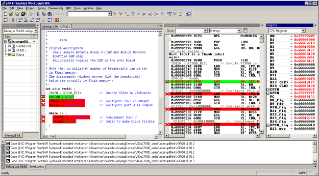
- IAR Embedded Workbench for ARM (EWARM)
- RealView® Microcontroller Development Kit (Keil MDK)
- Greenhills (GHS) MULTI
For more information about how to use RDI with debuggers listed above, please refer to the J-Link Manual (UM08001).
Unlimited Flash Breakpoints
The RDI DLL allows setting software breakpoints in flash memory areas, in the following called flash breakpoints. This makes it possible to set an unlimited number of flash breakpoints, rather than just the 2 hardware breakpoints permitted by the ICE. Setting flash breakpoints is executed very fast using a RAMcode specially designed for this purpose; on chips with fast flash the difference between breakpoints in RAM and Flash is unnoticeable.
More information about Unlimited Flash Breakpoints
RDI configuration
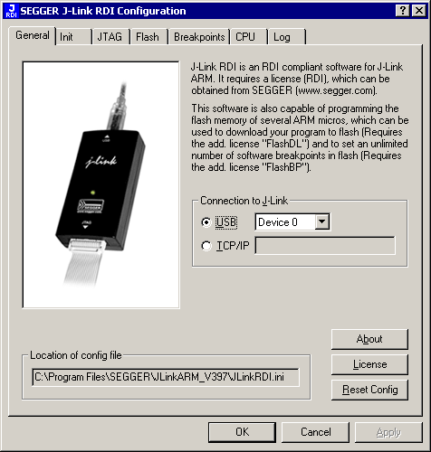
RDI allows various configuration settings, such as:
- Target system initialization via setup file
- JTAG Speed and scan chain settings
- Enable / disable Flash programming
- Breakpoint settings (use software breakpoints, use Unlimited Flash Breakpoints)
- CPU specific settings (Endianess, Reset strategy)
- Enable / Disable Logfiles
Commands in the setup file
| Command | Description |
|---|---|
| SetJTAGSpeed(x); | Sets the JTAG speed, x = speed in kHz (0=Auto) |
| Delay(x); | Waits a given time, x = delay in milliseconds |
| Reset(x); | Resets the target, x = delay in milliseconds |
| Go(); | Starts the ARM core |
| Halt(); | Halts the ARM core |
| Read8(Addr); | Reads a 8/16/32 bit value, Addr = address to read (as hex value) |
| Read16(Addr); | Reads a 8/16/32 bit value, Addr = address to read (as hex value) |
| Read32(Addr); | Reads a 8/16/32 bit value, Addr = address to read (as hex value) |
| Verify8(Addr, Data); | Verifies a 8/16/32 bit value, Addr = address to verify (as hex value) Data = data to verify (as hex value) |
| Verify16(Addr, Data); | Verifies a 8/16/32 bit value, Addr = address to verify (as hex value) Data = data to verify (as hex value) |
| Verify32(Addr, Data); | Verifies a 8/16/32 bit value, Addr = address to verify (as hex value) Data = data to verify (as hex value) |
| Write8(Addr, Data); | Writes a 8/16/32 bit value, Addr = address to write (as hex value) Data = data to write (as hex value) |
| Write16(Addr, Data); | Writes a 8/16/32 bit value, Addr = address to write (as hex value) Data = data to write (as hex value) |
| Write32(Addr, Data); | Writes a 8/16/32 bit value, Addr = address to write (as hex value) Data = data to write (as hex value) |
| WriteVerify8(Addr, Data); | Writes and verifies a 8/16/32 bit value, Addr = address to write (as hex value) Data = data to write (as hex value) |
| WriteVerify16(Addr, Data); | Writes and verifies a 8/16/32 bit value, Addr = address to write (as hex value) Data = data to write (as hex value) |
| WriteVerify32(Addr, Data); | Writes and verifies a 8/16/32 bit value, Addr = address to write (as hex value) Data = data to write (as hex value) |
| WriteRegister(Reg, Data); | Writes a register |
| WriteJTAG_IR(Cmd); | Writes the JTAG instruction register |
| WriteJTAG_DR(nBits, Data); | Writes the JTAG data register |
Example of a setup file
/*********************************************************************
*
*    Setup file for J-LINK RDI
*
**********************************************************************
* File:    LPC2294.setup
* Purpose: Setup for Philips LPC2294 chip
**********************************************************************
*/
SetJTAGSpeed(1000);
Reset(0);
Write32(0xE01FC040, 0x00000001); // Map User Flash into Vector area at (0-3f)
Write32(0xFFE00000, 0x20003CE3); // Setup CS0
Write32(0xE002C014, 0x0E6001E4); // Setup  PINSEL2 Register
SetJTAGSpeed(2000);
